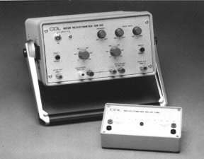
ROTOR REFLECTOMETER
Types TDR100,TDR100RB
A LOW VOLTAGE TEST UNIT FOR DETECTING WINDING
FAULTS IN POWER PLANT ALTERNATOR ROTORS
This semi-automatic equipment allows inter-turn and earth faults in the rotor windings of large electrical generators to be detected and located by a simple, rapid and safe low voltage test. The test may be carried out with the unexcited rotor winding stationary or at speed and is therefore particularly useful for detecting and locating faults which are speed dependent.
Typical applications include the routine testing of generators by power utilities and the monitoring by manufacturers and repairers of the rotor winding during its initial fabrication and any subsequent repair.
The Reflectometer may be left permanently connected to the rotor winding during re-insulation work, so that any defects are immediately apparent.
The equipment is easy to use and the adjustment of the controls is non-critical making it almost impossible to produce erroneous results due to maladjustment. The only additional item of equipment required to carry out the test is a single channel oscilloscope. The test should ideally be carried out on a routine basis so that any winding deterioration may be spotted and correlated with other effects such as increased excitation current or mechanical vibration.
The unit is housed in a two-tone grey metal case with adjustable carrying handle and is supplied complete with a set of connecting leads, contact magnets and a comprehensive manual containing examples of typical fault conditions. Also included is a Delay Line type DL100 which simulates a rotor winding and can be used to demonstrate the principle of operation of the Reflectometer. A padded carrying case is available, if required.
The TDR100RB has an additional internal rechargeable battery pack for use where mains supplies are not readily available.
PRINCIPLE OF OPERATION
A DC voltage step is applied to each end of the rotor winding in turn. Each reflected wave, at the input end of the winding, is monitored and the two waveforms are superimposed automatically and monitored on a single channel oscilloscope. As the half windings in a rotor are identical, the two waveforms monitored at each end of the rotor will also be identical for a healthy winding. Fig. 1 shows the two waveforms superimposed for a typical fault free winding.
A winding with a fault will cause different voltages to be monitored at the two ends and Fig. 2 shows a typical oscilloscope display for a winding with an inter-turn fault.
Photographic techniques are not required as the display is continuous.
A facility is included to allow the injection of pulses into either Slip Ring 1 or Slip Ring 2 as well as the normal 'AUTO' operating mode.
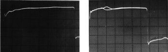
Fig 1. Fig 2.
SPECIFICATION
SUPPLY VOLTAGE 110V 50/60Hz or 220/240V 50/60Hz switchable.IMPEDANCE MATCHING RANGE 5 ohms to 500 ohms or 500 ohms to 1000 ohms.PULSE RATE 40Hz to 200Hz continuously variable.PULSE WIDTH 20µS to 400µS in three switched ranges.PULSE AMPLITUDE 12V.ENCLOSURE A two-tone grey metal case with adjustable carrying handle. Supplied complete with manual, leads, contact magnets and Delay Line (DL100).Dimensions: W: 305mm H: 152mm D: 355mm inc. handle.Weight: 5kg.TDR100RB As above with the addition of an internal maintenance free rechargeable Nickel Cadmium battery pack with an integral charger, giving over 15 hours continuous use under average operating conditions.
Convex Design Limited
email:sales@convexdesign.co.uk
Return to
Home Page
Rotor & Motor Test Equipment