ROTOR FLUX MONITOR
Type RFM100
The Rotor Flux Monitor allows continuous on load monitoring of the rotor (field) windings of power system generators for the detection of current-carrying inter-turn and double earth faults. The output of a search coil installed in the alternator air gap is automatically processed by the unit to produce a nulled waveform for a sound generator. A field winding with a current-carrying inter-turn fault will display a series of peaks in the nulled waveform corresponding to the position of the faulty coil slot. The technique has the advantage over most other methods in that continuous monitoring of the generator is possible and that only current carrying winding faults are detected. Moreover, a double earth fault (which is an extreme case of an inter-turn fault) may be detected directly if significant current flow occurs.
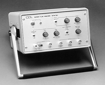
The unit is housed in a two-tone grey metal case with adjustable carrying handle and is supplied with a comprehensive manual containing examples of search coil waveforms.
A padded carrying case is available, if required.
PRINCIPLE OF OPERATION
The basis of the test is to compare the search coil voltage waveforms obtained from the two halves of the rotor winding. For a perfect winding, these two waveforms should be identical, although of opposite polarity. In practice it is extremely difficult to assess the two half waveforms directly on an oscilloscope screen as they do not occur simultaneously. The Rotor Flux Monitor delays the waveform so that the two half waveforms can be compared directly.
TYPICAL SEARCH COIL WAVEFORMS
Waveforms X and Y are the voltages induced by the conductors in each half of the rotor winding. The equipment delays waveform X by half the time for one revolution of the rotor. This delayed waveform is then added to waveform Y and the result shows any differences in the magnetic flux produced by each half winding.
PHOTO NOT YET AVAILABLE ![]()
X Y
SPECIFICATION
SUPPLY VOLTAGE 110V 50/60Hz or 220/240V 50/60Hz switchable.REFERENCE INPUT 110Vrms max. 50/60Hz.SEARCH COIL INPUT Sensitivity: 0.1Vrms (50Vrms max.) Impedance: High 1MW, Low 100KW.DELAY REFERENCE SIGNAL Delay signal in Manual mode Fine control by means of a 10-turn potentiometer. Delay signal in Auto mode Internal reference signal derived from the power supply. External reference signal applied via 4mm terminals.OUTPUTS (BNC) Reference Channel Delayed Channel: With AMPLITUDE control. Sum: Sum of Reference and Delayed Channels.ENCLOSURE A two-tone grey metal case with adjustable carrying handle. A padded carrying case is available, if required. Dimensions: W: 305mm H: 152mm D:355mm inc. handle. Weight: 5kg.
Convex Design Limited
email:sales@convexdesign.co.uk
Return to
Home Page
Rotor & Motor Test Equipment